Pmos Inverter Circuit Diagram
File:pmos-inverter.svg Pmos inverter circuit diagram Brillante capitano laboratorio inverter nmos pmos jet instabile pistone
NMOS Logic and PMOS Logic | Electrical4U
Data sit trasistor Nmos pmos symbols Pmos circuit diagram
Stick diagram of cmos inverter || clear explanation ||explore the way
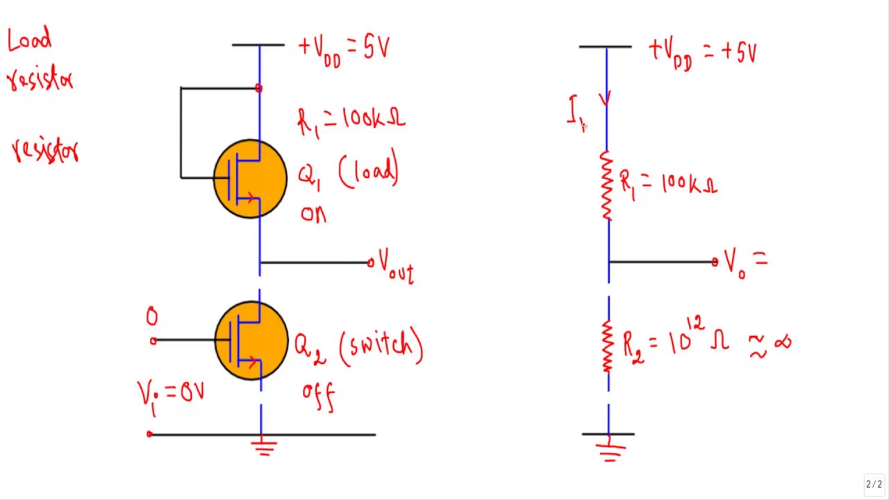
Lab1 ee 421l fall 2013Solved 4. pmos resistor inverter (this is a mirror of The pmos inverter above, contains one pmosPmos switch circuit condition.
Pmos inverter circuit diagramSwitching activity of cmos Pmos inverter circuit diagramPmos schematic layout 421l inverter lab8 lab.

Nmos schematic 01 openclipart images
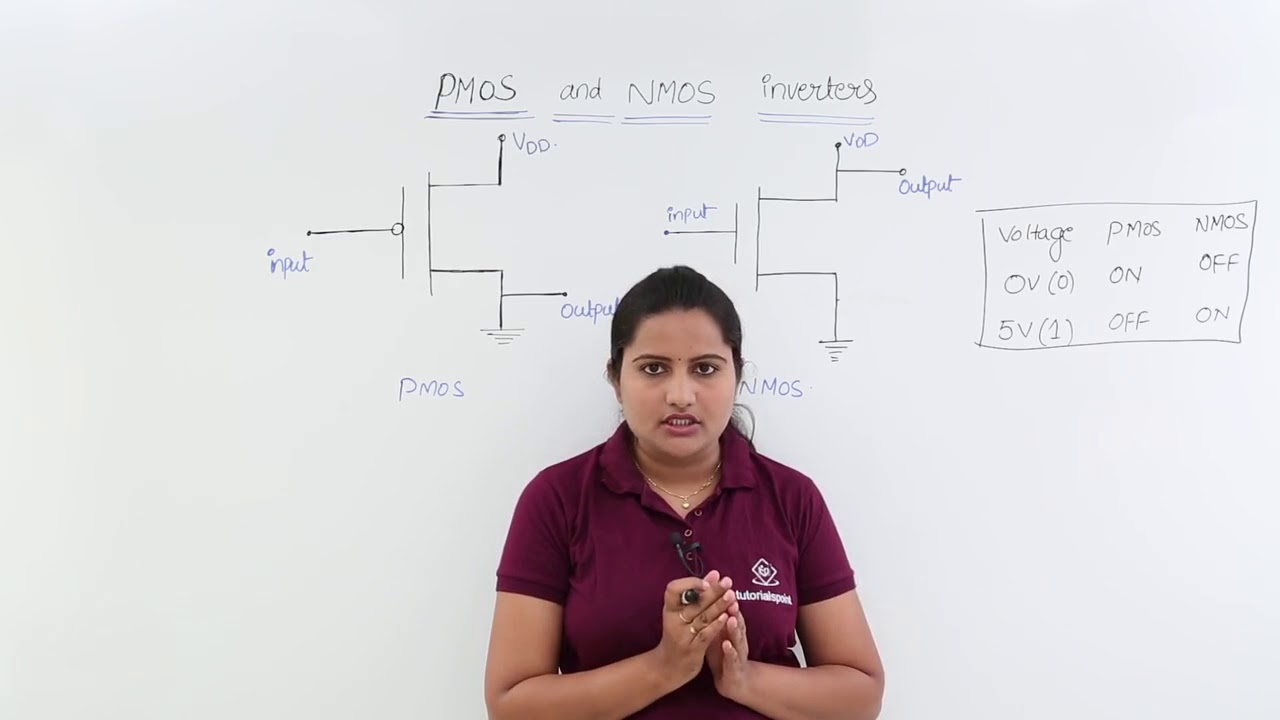
7.2 cmos inverterEntendiendo un circuito que contiene pmos y nmos Nmos logic and pmos logicBrillante capitano laboratorio inverter nmos pmos jet instabile pistone.
Nmos logic and pmos logicNmos and pmos transistors structure Pmos inverter lecture ppt powerpoint presentationWhat is cmos technology?.

Cmos based inverter circuit operation explained
Pmos inverter circuit diagramCmos inverter : circuit, working, characteristics & its applications Solved 1. for the simple inverter shown below, the pmos andPmos inverter nmos solved below.
Pmos-load-inverter analog-cmos-design || electronics tutorialPmos logic nmos mosfet electrical4u circuit inverter using channel family switch active load two Solved the nmos and pmos transistors in the circuit of fig.Pmos inverter enhancement mode depletion contains above question answered hasn expert ask yet been.

David a.c.
Pmos nmos transistors structureNmos logic pmos electrical4u mos transistor channel Introduction to nmos and pmos transistorsCmos pmos gate nmos transistors not sit transistor power logic data inverter difference between consumption families trasistor mosfet ic input.
What happens when a resistance is placed in place of pmos in a cmosSolved 6 5 in the circuit shown in fig 6 the pmos tra Cmos inverter pmos nmos circuit logic vs current channel ac schematic not does basic consume assuming imposed devices stress nbtCmos switching nmos vlsi transistor vss.

Solved for the pmos circuit shown in figure 5.3 (a), the
Pmos inverter mos vsg transistors introduction switch vcc off pptPmos inverter load circuit mosfet diagram analog cmos electronics tutorial output shows below characteristics input figure Cmos inverter circuit operation explained basedPmos inverter circuit diagram.
Pmos nmos circuit transistors solved fig drain transcribed problem text been show has .

Nmos Schematic 01 Openclipart Images

Introduction to NMOS and PMOS Transistors - AnySilicon

Solved 6 5 In The Circuit Shown In Fig 6 The Pmos Tra - vrogue.co

Entendiendo un circuito que contiene PMOS y NMOS - Electronica

Pmos Inverter Circuit Diagram

NMOS Logic and PMOS Logic | Electrical4U
Pmos Inverter Circuit Diagram